- Original article
- Published:
A numerical simulation on multi-spot pressure tensioning process of circular saw blade
Journal of Wood Science volume 61, pages 578–585 (2015)
Abstract
The multi-spot pressure tensioning process of circular saw blade was built by dynamic/explicit solution module of the finite element software called ABAQUS for avoiding non-convergence and improving the computational efficiency. The stress field of circular saw blade during loading process was calculated based on the finite element model. The model which could both meet the requirement of computational efficiency and accuracy was established by adjusting the step time and density of circular saw blade. The unloading process of circular saw blade was built by static/general solution module of ABAQUS using the stress field of loading process calculated by dynamic/explicit finite element method as initial conditions. The tangential tensioning stress field of circular saw blade tensioned by multi-spot pressure which showed the same trend with the measured result was calculated based on the two above-mentioned models. A more ideal distribution of tangential tensioning stress could be produced by the multi-spot pressure tensioning process. The feasibility of multi-spot pressure tensioning process was theoretically proved in this paper.
Introduction
With the rapid economic development and improvement of environmental protection awareness, every industry including wood industry has put forward the requirements of green manufacturing, energy-saving and emission reduction. Each wood processing enterprise has put forward higher requirements on the highly effective and sustainable use of wood. In the manufacturing field of furniture, wooden door and window, floor and other wood products, circular saw blade is an indispensable tool. Wood processing enterprises have placed greater demands on the cutting precision and material saving ability of circular saw blade.
When circular saw blade is cutting the work piece, tangential and radial tensile stresses are produced because of the centrifugal force generated by the higher rotational speed of circular saw blade. Meanwhile, thermal stress is produced because the temperature in the edge of circular saw blade is higher than other regions. The thermal stress will lead to a large tangential compressive stress in the edge of circular saw blade with the increase of temperature difference between the edge and center of circular saw blade, which could cause the buckling deformation of circular saw blade, reduction of cutting precision and machining quality of the surface, increase of kerf loss and shortening of saw life. The tensioning processes such as hammering, rolling and heating are proposed and applied in order to avoid the above-mentioned phenomenon. The tangential tensile tensioning stress field is produced during tensioning process in order to compensate the tangential compressive stress, which will improve the stability and quality of circular saw blade [1, 2]. Therefore, the tangential tensioning stress distribution after tensioning is the key factor that determines the quality of circular saw blade.
The tensioning stress distribution of circular saw blade after roll tensioning was described by Szymani [2]. In the inner loop of the tensioned region, the tangential tensioning stress is compressive, and its value increases gradually from loop of the tensioned region to inside. In the exterior loop of the tensioned region, the tangential tensioning stress is tensile, and its value decreases gradually from loop of the tensioned region to outside. This distribution of tangential tensioning stress is not very ideal relatively. The tangential tensioning stresses of circular saw blades tensioned by three levels of hammering were measured by X-ray stress meter [3, 4]. The tangential tensioning stress outside hammer region increases with radius, which is an ideal distribution. This phenomenon indicates that the distribution of tangential tensioning stress produced by hammering is more reasonable than that produced by roll tensioning. However, hammer tensioning has its limitations because the hammer tensioning creates a very irregular surface and produce localized, non-axisymmetric stresses because the force and position of spots are controlled by workers and its reproducibility and controllability are very difficult to be mastered, and it depends heavily on the experience and skills of saw repairing workers. The precision of hammer tensioning is relatively poor. Multi-spot pressure tensioning process is one kind of tensioning methods and a quasi-static process. The fixed areas of circular saw blade are pressed by spherical or cylindrical surface during multi-spot pressure tensioning process. The force and position of spots are controlled precisely by automated machinery during the multi-spot pressure tensioning process. A cyclic symmetry stress distribution and appropriate macroscopic deformation can be obtained by the multi-spot pressure tensioning process. Therefore, a more ideal distribution of tangential tensioning stress is produced during multi-spot pressure tensioning process. This tensioning approach is conducive to the realization of the automatic tensioning operation, especially in the production of ultra-thin circular saw blades.
At present, the studies on tensioning processes of circular saw blade mainly focus on the effect of tensioning process on dynamic stability of circular saw blade [5–15]. Only a few studies are about the generation process of tensioning stress during tensioning process. The theoretical model of roll tensioning process was established by Szymani. The tensioning stresses obtained by the model were generally in good agreement with the experimentally determined tensioning stresses [1]. The model of roll tensioning process was established by Nicoletti based on finite element method and the tensioning stresses were obtained, the introduction of these stresses into a modal analysis allowed us to predict the dynamic behavior of circular saw blade [16]. A finite element model for roll tensioning of circular saw blades which allowed the investigation of various roll tensioning parameters was developed by Heisel [17]. There is little theoretical research about the generation process of tensioning stress during multi-spot pressure tensioning process at present. For an in-depth research of generation process of tensioning stress during multi-spot pressure tensioning process, a numerical model which could both meet the requirement of computational efficiency and accuracy should be established first.
Therefore, the multi-spot pressure tensioning process of circular saw blade was built by dynamic/explicit solution module of ABAQUS in this paper. The step time and material density which can both meet the requirement of computational efficiency and accuracy were found for the dynamic/explicit model through numerical analysis. The unloading process of circular saw blade after tensioning was built by static/general solution module of ABAQUS using the stress field of loading process calculated by the dynamic/explicit method as initial conditions, and the tangential tensioning stress field of circular saw blade tensioned by multi-spot pressure was calculated by the two above-mentioned models. The correctness and rationality of the finite element model were proved in this paper. The feasibility of multi-spot pressure tensioning process was theoretically proved in this paper.
Theory
The basic theory of dynamic/explicit finite element method
The multi-spot pressure tensioning of circular saw blade is a process of quasi-static loading. A certain degree of elastoplastic deformation is produced in the interior of circular saw blade during this process. Theoretically, static/general finite element method should be used to simulate this process. However, complex contact problems need to be dealt in the simulation of multi-spot pressure tensioning process. The frictional contact boundary condition is applied by penalty function in static/general finite element method, which will lead to a huge amount of computation, low computation efficiency and sometimes non-convergence. It is hard to ensure the stability calculation by adjusting the model parameters. Due to the disadvantages of static/general finite element method in simulating multi-spot pressure tensioning process, dynamic/explicit finite element method was chosen to simulate this process. A result similar to quasi-static loading process can be obtained by dynamic/explicit finite element method through adjusting model parameters like step time and material density. Moreover, kinetic friction is used in dynamic/explicit finite element method which can avoid convergence and the efficiency of computation can be improved obviously by adjusting step time and material density. Therefore, the loading process of multi-spot pressure tensioning process of circular saw blade was built by dynamic/explicit finite element method in this paper.
In the problems of dynamics, solving equation of the system is shown in the following equation.
where \( \textit{\"{a}}\left( t \right) \), \( \dot{a}\left( t \right) \) and \( a\left( t \right) \) are the nodal acceleration vector, nodal velocity vector and nodal displacement vector of system. M, C, K and \( Q\left( t \right) \) which are integrated by the element matrix and vector of each are the mass matrix, damping matrix, stiffness matrix and nodal load vector of system, as shown below.
where M e, C e, K e and Q e are the mass matrix, damping matrix, stiffness matrix and load vector of element. The solving process of dynamic/explicit is based on the central difference algorithm. Acceleration and velocity can be expressed by displacement, as shown below:
The recurrence equation of the central difference algorithm is obtained by putting the expression of acceleration and velocity into the equation of motion, as shown below:
In order to guarantee the stability calculation, time increment \( \Delta t \) should satisfy the following equation:
In Eq. 5, \( \Delta t_{\text{cr}} \) is the critical time increment of system and \( T_{\text{n}} \) is the smallest natural vibration period of system.
It can be proved theoretically that \( T_{\text{n}} \) is always greater than or equal to the smallest natural vibration period of the minimum size unit. The minimum length L of the minimum size unit can be found after the unit grid delineation. T n can be expressed as the following equation approximately. C is the propagation velocity of acoustic wave, E is elastic modulus and ρ is medium density. Their relationships are shown below:
Although the dynamic explicit scheme is conditionally stable and limited by the minimum time increment of system, the contact problems can be easily solved using the minimum time increment of system, especially for the complex contact problems.
The basic theory of static/general finite element method
When the unloading process of circular saw blade is simulated by dynamic/explicit finite element method, a lot of step time is needed to get a stable result, which leads to a very low computational efficiency. Tensioning stress distribution of circular saw blade after unloading process can be calculated by static/general finite element method using the stress field of loading process calculated by dynamic/explicit finite element method as initial conditions because the unloading process is a linear elastic mechanical behavior.
Static/general finite element method is not affected by the step time because the inertia force and the damping effect are not considered. The response of the system is fixed. The equation of system is shown below:
where K is the total stiffness matrix applied by displacement boundary conditions, a is the nodal displacement vector, P is the equivalent load vector. The equation of P is shown below:
where \( P_{\text{F}} \) is the concentrated force applied to nodes directly. \( P_{\text{f}}^{\text{e}} \) is the nodal load matrix equivalent to the volume force f which is applied to each element. \( P_{\text{S}}^{\text{e}} \) is the nodal load matrix equivalent to the distributed force T which is applied to boundary \( S_{\sigma }^{\text{e}} \) of elements. \( P_{{\sigma_{0} }}^{\text{e}} \) and \( P_{{\varepsilon_{0} }}^{\text{e}} \) are the nodal load matrix equivalent to the initial stress \( \sigma_{0} \) and initial strain \( \varepsilon_{0} \) of elements. They are shown below:
where B is the strain matrix, D is the elastic matrix, \( V_{\text{e}} \) is the volume of element. The total stiffness matrix which is not applied by displacement boundary conditions is expressed by the element stiffness matrix, as shown below:
The nodal displacement vector a is obtained by solving Eq. 7. The element strain and stress can also be obtained by solving equations shown below:
Materials and methods
The test of tangential tensioning stress distribution
The tangential tensioning stress distribution was the focus because the tangential tensioning stress distribution was the key factor that determined the performance of circular saw blade. As shown below, an experiment was designed to prove that the tangential tensioning stress of circular saw blade calculated by finite element method in this paper was true and reliable. Parameters of circular saw blade were shown below: material, 65Mn; hardness, HRC42; diameter, 356 mm; thickness, 2.2 mm; the diameter of the hole, 30 mm. Parameters of the spherical pressure head were shown below: hardness, HRC60; radius, 70 mm. The distribution of spots is shown in Fig. 1. The loading force was 100.0 kN. As shown in Fig. 1, line a, line b and line c were inserted in specified radial path of circular saw blade. There were 14 points in each line. Each point was numbered 1–14 from the inside to the outside, respectively. Among them, the distance between first point and center of circular saw blade was 38 mm. The distance between each point was 10 mm. In order to improve the test precision, the tangential tensioning stress of each point was tested twice by X-ray stress meter, as shown in Fig. 2. The average value of the test results of the points with the same number was the final tangential tensioning stress.

Distribution of spots of circular saw blade

X-ray stress meter
The modeling of the multi-spot pressure tensioning process based on dynamic/explicit
-
1.
The geometric model A half model was established considering the symmetry of the model and the spherical pressure head was established with corresponding size, as shown in Fig. 3. “RP” represented the reference point of the spherical pressure head.
Fig. 3 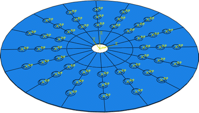
Geometric model of the multi-spot pressure tensioning process (“RP” represented the reference point of the spherical pressure head)
-
2.
The material model The elastic deformation of the spherical pressure head was not considered in the finite element model, so the spherical pressure head was modeled as analytical rigid body; The material model of circular saw blade was set as linear strengthening elastic–plastic model (bilinear model) because the plastic deformation of circular saw blade during multi-spot pressure tensioning process was very little, probably less than 0.15. Its yield strength was 430 MPa and the strain hardening rate was 1000 MPa. The equivalent plastic strain was 0 when the Mises stress was 430 MPa. The equivalent plastic strain was 0.2 when the Mises stress was 630 MPa. Its elastic modulus and Poisson ratio were 210 GPa and 0.3.
-
3.
The constraints Displacement constraint of Z direction was applied to the axial center plane of circular saw blade; coupling constraint was applied to the inner wall of the center hole of circular saw blade. The constraint point was the center of circular saw blade and all of its degrees of freedom were constrained. The loading force was applied to the spherical pressure head. The loading force was increased linearly with the step time. The maximum loading force was obtained by test measurement. All indentations were made simultaneously because the effect between the local plastic deformation behaviors of different pressure positions was very little. The situation of all indentations made simultaneously was assumed to be similar to the situation of indentations made one by one. This kind of loading could also greatly reduce the step time, improve the efficiency of calculation and simplify the model.
-
4.
Meshing The spherical pressure head was not meshed because it was modeled as analytical rigid body. The element C3D8R was chosen for circular saw blade. The number of element in the contact zone between the circular saw blade and spherical pressure head was increased for avoiding hourglass phenomenon. The model after meshing is shown in Fig. 4. “RP” represented the reference point of the spherical pressure head.
Fig. 4 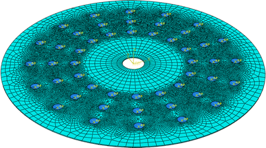
Meshing of finite element model (“RP” represented the reference point of the spherical pressure head)
-
5.
Contrast between artificial strain energy, internal energy and kinetic energy The stress field of circular saw blade during loading process was calculated by the dynamic/explicit finite element model, as shown in Fig. 5. The values of artificial strain energy, internal energy and kinetic energy should be compared to ensure the rationality of the model. The contrast between artificial strain energy, internal energy and kinetic energy is shown in Fig. 6. The artificial strain energy and kinetic energy were far less than the internal energy, which showed the rationality of the model.
Fig. 5 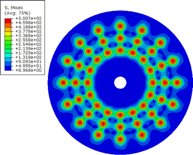
Stress field of circular saw blade during loading process
Fig. 6 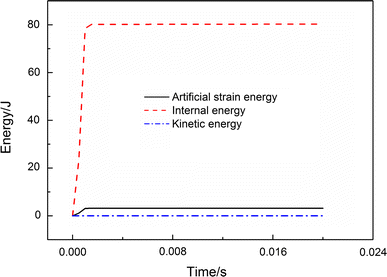
Contrast between artificial strain energy, internal energy and kinetic energy


Results
Analysis of the factors affecting the calculation efficiency and result of the dynamic/explicit model
The multi-spot pressure tensioning process of circular saw blade was built by dynamic/explicit solution module of ABAQUS in this paper. The changes of calculation time and result were observed by adjusting the step time and density of circular saw blade. The purpose of this paper was to choose the suitable time and density for the dynamic model of multi-spot pressure tensioning process, which could both meet the requirement of computational efficiency and accuracy. In the following part, the “t” represented the unit “tonne” of weight.
Conditions: the density of circular saw blade was 7.8 × 10⁻⁹ t/mm3; a series of step time included 0.00005, 0.0001, 0.0005, 0.001, 0.005, 0.01 s; the loading force was 50.0 kN.
As shown in Fig. 7, when the step time was between 0.00005 and 0.0001 s, the tangential stress distribution in specified radial path of circular saw blade changed greatly with the step time. It showed that the step time had great effect on the tangential stress field of circular saw blade in such cases. The influence of inertia force could not be ignored and the calculation result could not be equal to the result of process of quasi-static loading. When the step time was between 0.0005 and 0.01 s, the change of the tangential stress distribution in specified radial path of circular saw blade was very small with the step time. It showed that the step time had very little effect on the tangential stress field of circular saw blade in such cases. The influence of inertia force could be ignored and the calculation result could be equal to the result of process of quasi-static loading.

Effect of step time on tangential stress distribution
As shown in Fig. 8, the calculation time of the finite element model built by dynamic/explicit was increased with the step time. Therefore, the step time of model of multi-spot pressure tensioning process was determined as 0.001 s considering the result of tangential stress distribution in specified radial path of circular saw blade, which could both meet the requirements of computational efficiency and accuracy.

Effect of step time on calculation time
Conditions: a series of the density of circular saw blade included 7.8 × 10⁻⁹, 7.8 × 10⁻⁸, 7.8 × 10⁻⁷, 7.8 × 10⁻⁶ t/mm3; the step time was 0.001 s; The loading force was 50.0 kN.
As shown in Fig. 9, the tangential stress distribution in specified radial path of circular saw blade changed greatly with the increase of density of circular saw blade. It showed that the density of circular saw blade had great effect on the tangential stress field of circular saw blade. When the density of circular saw blade was closing to the true density, the tangential stress distribution in specified radial path of circular saw blade tended to be stable and no longer changed.

Effect of density of circular saw blade on tangential stress distribution
In dynamic/explicit solution module of ABAQUS, the mass density of steel could be changed in a reasonable range for improving calculation efficiency as shown in the second chapter. As shown in Fig. 10, speed of sound wave propagation in circular saw blade decreased with the density of circular saw blade, which led to the increase of the smallest natural vibration period directly. The time increment increased when the step time was fixed. Therefore, the calculation time of the finite element model built by dynamic/explicit decreased greatly with the density of circular saw blade, and the computational efficiency was improved greatly. The density of circular saw blade was determined as 7.8 × 10⁻⁹ t/mm3 considering both the result of tangential stress distribution in specified radial path of circular saw blade and computational efficiency.

Effect of density of circular saw blade on calculation time
Contrast between the tangential tensioning stress of circular saw blade after unloading and the measured results
The loading process of multi-spot pressure tensioning was built by dynamic/explicit solution module of the finite element software called ABAQUS. The appropriate step time and material density which could both meet the requirement of computational efficiency and accuracy were found for the dynamic/explicit finite element model. Tensioning stress distribution of circular saw blade after unloading process could be calculated by static/general finite element method using the stress field of loading process calculated by dynamic/explicit finite element method as initial conditions.
The contrast between the tangential tensioning stress of circular saw blade after unloading and the measured results in specified radial path of circular saw blade is shown in Fig. 11.

Contrast between the simulation and the measured result
As shown in Fig. 11, the tangential tensioning stress distribution of circular saw blade after unloading and the measured results in specified radial path of circular saw blade had the same trend and the value was similar in most regions, which proved that the tangential tensioning stress of circular saw blade calculated by finite element method in this paper was true and reliable. In the edge area of circular saw blade, the tangential tensioning stress was increased with the ratio of radius, and the feasibility of multi-spot pressure tensioning process was theoretically proved.
Discussion
The multi-spot pressure tensioning process of circular saw blade was built by dynamic/explicit solution module of ABAQUS in this paper. The tangential stress field of circular saw blade during loading process was calculated through the model. The linear elastic unloading process of circular saw blade with initial stress field calculated by the dynamic/explicit model was established by static/general solution module. The tangential tensioning stress of circular saw blade after unloading was finally obtained by the above-mentioned two models. Compared with the experimental results, the simulation result proved to be true and reliable.
Based on the basic theory of dynamic/explicit finite element method and characteristics of multi-spot pressure tensioning process of circular saw blade, the calculation efficiency and results were optimized by adjusting the step time and density of circular saw blade. The simulation results showed that the model could meet the requirements of computational efficiency and accuracy when the step time was 0.001 s and the density of circular saw blade was 7.8 × 10⁻⁹ t/mm3. The calculation time was about 800 s. The model of multi-spot pressure tensioning process of circular saw blade in this paper could make up the defects of low efficiency and convergence of static/general finite element method in solving complex contact problems, which laid the theoretical foundation for the future research of multi-spot pressure tensioning process.
The tangential tensioning stress field of circular saw blade was calculated by the finite element model in this paper. In the edge area of circular saw blade, the tangential tensioning stress increased with the increase of the ratio of radius, which was the ideal distribution. The feasibility of multi-spot pressure tensioning process was theoretically proved.
References
Zhang ZK (2004) Testing methods of circular saw blade tension. J Wood Process Mach 2:1–5
Szymani R, Mote CD Jr (1979) Theoretical and experimental analysis of circular saw tensioning. Wood Sci Technol 13(3):211–237
Umetsu J, Noguchi M, Wada K, Fujii Y (1989) Confirmation of φ splitting in the distribution of residual stress in tensioning circular saws. Mokuzai Gakkaishi 35:856–858
Umetsu J, Noguchi M, Matsumoto I (1994) Measuring residual stresses in tensioned circular saws using X-rays (in Japanese). Mokuzai Gakkaishi 40:268–273
Szymani R, Mote CD Jr (1974) A review of residual stresses and tensioning in circular saws. Wood Sci Technol 8(2):148–161
Schajer GS, Mote CD Jr (1983) Analysis of roll tensioning and its influence on circular saw stability. Wood Sci Technol 17(4):287–302
Schajer GS, Mote CD Jr (1984) Analysis of optimal roll tensioning for circular saw stability. Wood Fiber Sci 16(3):323–338
Ishihara M, Noda N, Ootao Y (2010) Analysis of dynamic characteristics of rotating circular saw subjected to thermal loading and tensioning. J Therm Stress 33(5):501–517
Ishihara M, Murakami H, Ootao Y (2012) Genetic algorithm optimization for tensioning in a rotating circular saw under a thermal load. J Therm Stress 35(12):1057–1075
Stakhiev YM (2004) Coordination of saw blade tensioning with rotation speed: myth or reality. Holz Roh Werkst 62(4):313–315
Carlin JF, Appl FC, Bridwell HC (1975) Effects of tensioning on buckling and vibration of circular saw blades. J Eng Ind 97(1):37–48
Schajer GS, Kishimoto KJ (1996) High-speed circular sawing using temporary tensioning. Holz Roh Werkst 54(6):361–367
Cristóvão L, Ekeva M, Grönlund A (2012) Natural frequencies of roll-tensioned circular saw blades: effects of roller loads, number of grooves, and groove positions. BioResources 7(2):2209–2219
Gospodaric B, Bucar B, Fajdiga G (2015) Active vibration control of circular saw blades. Eur J Wood Wood Prod 73(2):151–158
Zhang MS, Zhang Y, Ke JJ, Li XW, Cheng LB (2014) The influence of tangential roller pressure on the stability of circular saw blade. Appl Mech Mater 614:32–35
Nicoletti N, Fendeleur D, Nilly L, Renner M (1996) Using finite elements to model circular saw roll tensioning. Holz Roh Werkst 54(2):99–104
Heisel U, Stehle T, Ghassemi H (2014) A simulation model for analysis of roll tensioning of circular saw blade. Adv Mater Res 2014:57–66
Acknowledgments
We gratefully acknowledge the financial support of National Natural Science Foundation of China (No. 31270605) and Agricultural Science Technology Achievement Transformation Fund of China (No. 2013G B24320607).
Author information
Authors and Affiliations
Corresponding author
Rights and permissions
About this article

Cite this article
Li, B., Zhang, Z., Li, W. et al. A numerical simulation on multi-spot pressure tensioning process of circular saw blade. J Wood Sci 61, 578–585 (2015). https://doi.org/10.1007/s10086-015-1508-5
Received:
Accepted:
Published:
Issue Date:
DOI: https://doi.org/10.1007/s10086-015-1508-5